|
|
Footer


CHAPTER 4 | Layout
‘Layout’ refers to cooling tower orientation for optimum airflow. Obstructions- walls, I-beams, and the like- can cause two problems:
#1 Recirculation is a phenomenon where the moist discharge air is somehow redirected back into the air inlet. The increased moisture in the air inhibits evaporation and reduces cooling capacity. [As demonstrated earlier (Ch.1), the whole point is to vaporize as much water as possible so as to reject approximately 1,000BTU for each pound of water evaporated]. For existing installations, the increased moisture is evidenced by an elevated wet bulb temperature reading near the cooling tower air inlet. The detrimental effect of increased wet bulb is best demonstrated by examining cooling tower selection charts. A cooling tower selected at 78 degree wet bulb is about 40% bigger than one selected at 72 degree wet bulb [@ 95 in and 85 out].
#2 Starving the tower for air. Reducing the airflow inhibits the tower’s ability to evaporate water and thermal capacity suffers accordingly.
To prevent recirculation and starving, cooling towers should be installed to be free flowing. The air discharge must be elevated above any adjacent walls to reduce the potential for prevailing winds to cause recirculation. This can mean elevating the tower or extending the discharge by ducting. Centrifugal towers can accept tapered discharge hoods- basically, velocity accelerators- that blast the moist air away from the tower. Such hoods require the tower to be fitted with oversize motor(s) to handle the extra duty.
Obstacles such as I-beams should be well away from the inlet and discharge air streams. This is particularly important for prop fan, draw thru cooling towers where the discharge air pattern ‘cork screws’ away from the tower. Even a small obstruction can destroy the discharge pattern greatly increasing the likelihood for recirculation. Even, discharge screens should be eliminated when not required for safety. [Discharge cylinders over 6’ tall do not require screens].
Ducting should be free flowing and symmetrical.
Additional rules have been developed for three classic layout scenarios... The Well, the Wall and the Louvered Enclosure.
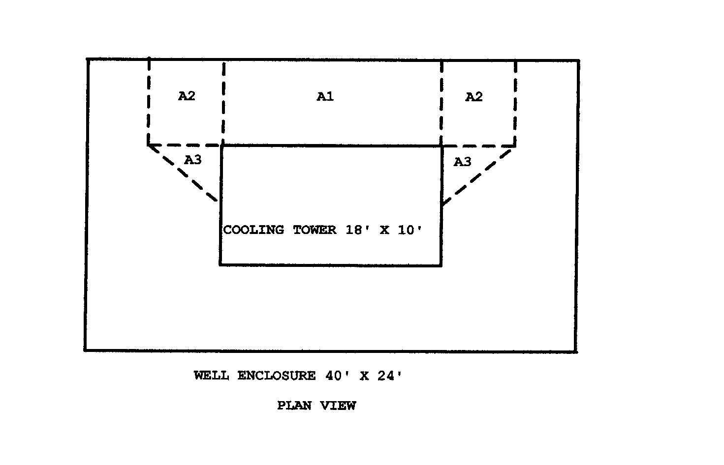
The Well is a solid, four wall enclosure where all the inlet air enters vertically downward. The maximum downward velocity is typically limited to 300ft./min.. The useable area is:
A) The space between the air inlet and the enclosure.
B) the space 50% beyond the air inlet length on each side when adjacent to a non air entry side [but no more than 6’] and,
C) the triangular wedge on any non air inlet side. Note: do not double count any overlapping areas for multiple inlet towers.
Example: A cooling tower is 18’ long, 10’ wide, has 86,000CFM air entry along one long side and is centered in a 40’ x 24’ well. Is this OK?

|
| A1=7'X18' |
=126Sq.Ft. |
| A2=6'x7'x2 |
=84Sq.Ft. |
| A3=6'X10' |
=60Sq.Ft. |
| Total |
=279Sq.Ft. |
| Velocity=86,000cfm/270Sq.Ft=319ft./min. |
|
The installation is a little too restrictive. The tower can be moved further from the wall along the air intake side. It should be moved as far from the wall as possible without violating maintenance requirements.
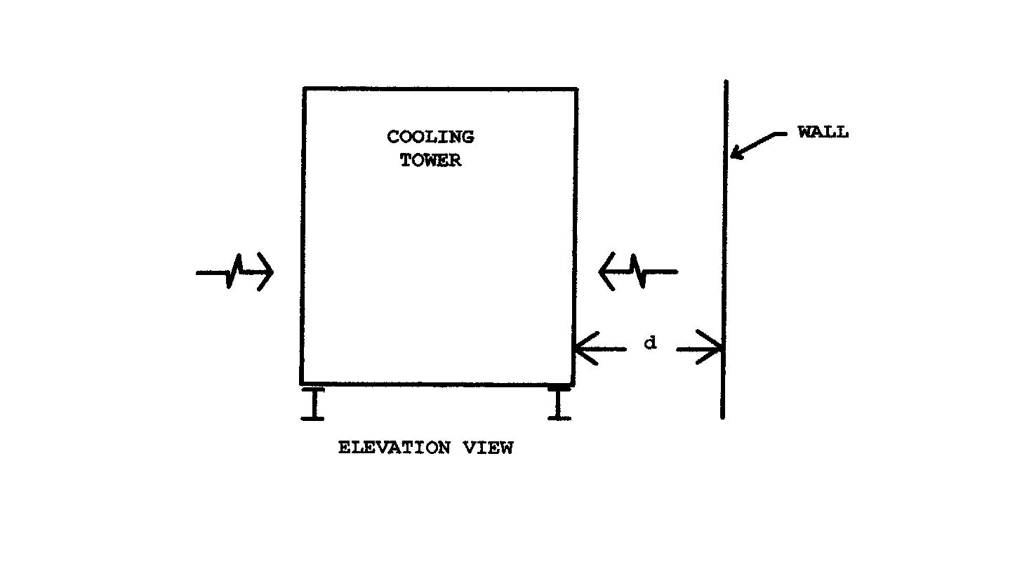
The Wall is a solid obstruction parallel to and at some distance from an air inlet face. If the wall is too close, the tower will be forced to draw air vertically down through the narrow space between the cooling tower and the wall increasing the likelihood of recirculation. To minimize this velocity, the tower is located far enough from the wall for all of the air to flow horizontally in the space at no more than 600Ft./Min..
Example: A dual sided air inlet cooling tower is 10’ tall, elevated 1’ on I-beams and ingests 72,000cfm of air. What is the minimum distance ‘d’ between one of the air inlet sides and a solid wall?

Velocity = CFM / Area
600 = [72,000CFM x 1/2] / (10’ + 1’) d
d = 5.5’ (where d = distance from wall)
The Louvered Enclosure is similar to the previous examples except air can pass through. Typically the louvers are sheet metal blades used to ‘hide’ the cooling tower. The designer first examines a louvered enclosure as though it were a wall or well. If it passes these more stringent requirements, it is ok. If not, louvers and cooling towers must have the following characteristics:
-50% net free louver area.
-Cooling tower air inlets must face the louvers.
-All the air is assumed to pass through the louvers at no more than 600ft/min.. (Do not assume any downward air flow.)
-Minimum distance between a cooling tower and a louver is 4’ for towers under 300 tons and 6’ for towers up to 4,000 tons.
Example: Instead of a solid wall, the previous cooling tower has 50% net free area louvers 12’long x 11’ tall. Are the louvers adequately sized?
CFM / (net free louver area) = [72,000 x 1/2] / (12 x 11 x 50%) = 545 Ft./Min. ... OK.
The suggested guidelines outlined here should be overridden by manufacturer requirements. When faced by a tight ‘enclosure’, the designer should request review by the cooling tower manufacturer.
Remember that optimum cooling tower location is also influenced by hydraulic requirements, sound, etc..
| |